
- All
- Product Name
- Product Keyword
- Product Model
- Product Summary
- Product Description
- Multi Field Search
Views: 0 Author: Site Editor Publish Time: 2026-07-31 Origin: Site


The transition from manual or semi-automated processes to robotic tufting is driven by the need for scale, speed, and consistency. Operations managers increasingly rely on automation to meet growing market demands without sacrificing product quality. However, evaluating technical specifications often leads to misguided priorities.
While speed and needle stroke rates usually dominate spec sheets, X/Y positioning accuracy is the actual limiting factor for design resolution, material yield, and long-term machine reliability. Microscopic deviations compound quickly during operation. These small misalignments turn into massive production bottlenecks, causing costly rework and material waste.
For operations managers and technical buyers, evaluating the structural and software components driving positioning accuracy is critical. You must avoid poor equipment investments. In this article, you will learn how mechanical tolerances impact final pile density. You will also discover actionable criteria to properly evaluate frame rigidity and software control systems.
Yield and ROI: Variations in X/Y positioning directly correlate to inconsistent pile density and increased yarn waste.
Repeatability vs. Accuracy: A highly repeatable machine that is consistently inaccurate still produces defective batches; buyers must evaluate both metrics.
Structural Integrity: Real-world accuracy degrades under operational stress (vibration, high-speed movement); rigid X-Y gantry frames generally offer more stable long-term precision than standard articulated robotic arms for flat-plane tufting.
Evaluation Criteria: Shortlisting should focus on closed-loop feedback systems, frame rigidity, and dynamic calibration capabilities, not just theoretical out-of-the-box specifications.
Microscopic deviations might seem harmless on paper. However, they compound aggressively over a full production run. A toolhead drifting by just fractions of a millimeter on every stroke quickly creates systemic errors. When you multiply a tiny deviation by tens of thousands of tufting cycles, you get highly visible flaws. Minor mechanical slop directly degrades your final product quality.
Inaccurate step-overs in the X or Y axis lead directly to uneven yarn distribution. If the toolhead travels slightly too far, you get sparse patches exposing the backing cloth. If it falls short, you encounter dense yarn bunching. This uneven distribution creates visible striping across the rug surface. To prevent these visual defects, operations must maintain optimal tufting machine positioning accuracy at all times.
When machines leave gaps, operators frequently resort to over-tufting. They force extra yarn into the backing to hide sparse patches. This practice consumes excess material and artificially inflates your yarn expenses. Furthermore, correcting defects demands intensive manual labor. Workers spend hours manually trimming, re-tufting, or inspecting flawed batches. In severe cases, the ruined backing cloth goes straight into the dumpster.
A successful investment must demonstrably reduce batch-to-batch variation. Quality hardware holds tight tolerances under continuous, high-speed operation. You achieve true success when your machine delivers identical results on Monday morning and Friday afternoon. Minimizing these structural variations protects your profit margins and eliminates constant manual intervention.
We must first define what X/Y positioning accuracy actually means. In the context of robotic tufting, it refers to the exactness of the toolhead reaching a commanded coordinate. If the software commands the needle to move precisely ten millimeters to the right, accuracy measures how closely the physical hardware hits that exact ten-millimeter mark.
Buyers often confuse absolute accuracy and repeatability. You need both to ensure consistent quality.
Absolute Accuracy: This measures how closely the machine hits a specific programmed point in space. It represents the baseline correctness of the motion system.
Repeatability: This measures the ability to return to that exact point consistently over thousands of cycles. A machine can be highly repeatable but terribly inaccurate, continually hitting the wrong spot with perfect consistency.
We must also look at the foundational architecture of the equipment. X-Y gantry systems use linear guide rails mounted on a rigid frame. Articulated 6-axis robots resemble human arms and operate from a single base pivot. Rigid planar gantries typically offer superior structural stiffness for high-force applications. Tufting generates heavy vertical resistance. Linear gantries absorb this downward force much better than extended robotic joints.
System Architecture | Primary Motion Mechanism | Stiffness & Deflection Resistance | Ideal Tufting Application |
|---|---|---|---|
X-Y Gantry System | Linear guide rails and ball screws/belts | Very High. Minimal deflection under vertical load. | High-speed flat-plane rug tufting. |
Articulated 6-Axis Robot | Rotary joints and harmonic drives | Moderate. Prone to micro-bending at full extension. | Multi-angle, 3D surface tufting. |
Understanding these mechanical limits helps you choose the right foundational setup. Investing in a highly stable architecture prevents endless troubleshooting down the road. Every reliable precision tufting machine relies on robust engineering principles to resist the aggressive forces generated during production.
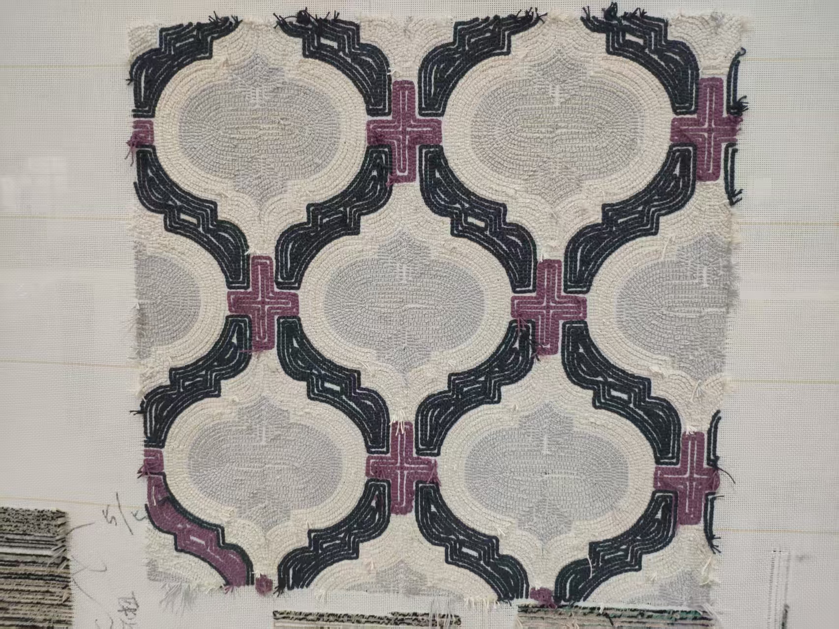
A machine's technical specifications directly dictate its creative limits. Complex geometries require pinpoint needle placement. When tufting intricate, multi-color patterns, you cannot afford any design bleeding. Sharp curves and precise geometric angles rely entirely on the hardware accurately translating digital coordinates into physical movements. If the toolhead drifts, colors blend poorly, ruining custom designs and brand logos.
Accurate needle placement also protects your backing materials. Primary backing fabrics endure immense stress during production. If a needle repeatedly strikes too closely to previous holes, it destroys the warp and weft fibers. This excessive localized tension tears the fabric. It also warps the entire canvas, causing the rug to curl or buckle during the final finishing stages.
We must address the crucial relationship between speed and accuracy. High stroke rates look impressive in marketing brochures. However, pushing a toolhead rapidly across a frame generates tremendous inertia. Budget systems cannot control this momentum. When they run at high speeds, they overshoot their target coordinates. Operators must slow these cheaper machines down significantly to prevent toolhead drifting and maintain acceptable quality.
Top-tier equipment maintains tight X/Y tolerances even at maximum stroke speeds. They utilize advanced braking and acceleration curves to control inertial forces. This dynamic control ensures the needle stops exactly where intended, regardless of the travel speed. Investing in premium Tufting Machines allows you to maximize daily throughput without sacrificing the crisp resolution of your textile designs.
We must acknowledge the harsh operational realities of textile manufacturing. Out-of-the-box specifications represent a machine in its purest, most optimal state. Once deployed on a factory floor, these mechanical components face relentless abuse. Recognizing what degrades hardware over time allows you to implement proactive maintenance strategies.
Mechanical backlash and wear introduce significant play into the motion system over time. Bearings wear down. Drive belts stretch under continuous tension. Rack-and-pinion systems lose their tight meshing. This gradual degradation creates "slop" or "backlash" in the drive train. When the motor reverses direction, this tiny gap causes a slight delay in movement. This delay translates directly into coordinate errors on the backing cloth.
Vibration and resonance pose another massive threat. The aggressive reciprocating motion of the tufting needle generates violent kinetic energy. The entire frame absorbs these shockwaves hundreds of times per minute. If the frame lacks sufficient dampening, these vibrations deflect the X/Y axes. The toolhead literally shakes off its target. Lightweight frames often hit harmonic resonance, magnifying the shaking to destructive levels.
Calibration drift remains an unavoidable reality. Thermal expansion causes metal rails to grow and shrink with temperature shifts. Concrete floors settle and shift subtly under heavy loads. Continuous payload shifts from heavy yarn cones also alter the machine's center of gravity. You must assume baseline specs will degrade. Facilities require ongoing calibration routines and proactive mechanical adjustments to sustain original precision levels.
Evaluating automation equipment requires looking past the glossy marketing claims. You must scrutinize the underlying engineering. Focus on components managing motion, resisting stress, and correcting errors. Technical buyers should systematically evaluate several crucial dimensions before requesting a final quote.
Drive Systems: Always look for AC servo motors paired with closed-loop absolute encoders. Avoid open-loop stepper motors. Steppers often lose their physical position when pushed hard. Closed-loop systems constantly verify the toolhead location and correct errors instantly.
Structural Rigidity: Assess the weight and material composition of the main gantry. Heavy-duty welded steel absorbs tufting vibrations far better than lightweight aluminum extrusions. Mass provides the necessary dampening to keep the needle steady.
Software Compensation: Superior hardware still needs intelligent software. Evaluate the control system. Does it include dynamic error mapping? Look for tension-compensation algorithms predicting and correcting mechanical deflection in real-time.
Vendor scrutiny must extend beyond basic showroom demonstrations. Do not rely solely on optimal-condition demo videos. Vendors typically showcase their equipment using perfectly tensioned, premium materials. You should demand physical pilot runs using your specific backing materials and your heaviest yarn types. Push the robotic tufting machine hard during these tests to reveal its true operational limits.
Finally, establish a framework for cross-comparing vendor quotes. Look beyond the initial purchase price. Evaluate the practical reality of maintaining accuracy over a five-year lifecycle. Consider the cost of preventative maintenance parts, like replacement belts and bearings. Evaluate whether the manufacturer provides intuitive calibration tooling. A cheaper machine often demands expensive, frequent mechanical interventions just to remain operational.
X/Y positioning accuracy serves as the foundational metric dictating your machine's true production capacity. It directly influences your material yield, design resolution, and operational efficiency. Ignoring this metric in favor of raw speed guarantees a cycle of constant rework and wasted textiles.
Buyers should confidently prioritize structural rigidity and closed-loop servo control. Heavy steel frames and intelligent drive systems resist the punishing vibrations of continuous tufting. Furthermore, understanding the realistic maintenance requirements ensures your equipment holds its tight tolerances year after year.
Take action today by auditing your current defect rates. Analyze how much yarn and backing you lose to inconsistent tufting density. Contact an experienced sales engineering team for a technical consultation. Discuss your specific design tolerances to find a machine built to handle your exact production demands.
A: Industry-standard tolerance ranges typically fall between 0.1mm and 0.5mm. The ideal specification depends heavily on your application. High-density rugs with intricate, multi-color logos require accuracy closer to 0.1mm to prevent color bleeding. Basic geometric patterns or single-color fill areas can operate successfully at 0.5mm tolerances.
A: High speeds generate massive inertial loads. When the heavy toolhead moves rapidly, momentum forces it past the target coordinate. Open-loop stepper motors cannot detect this overshoot. Additionally, aggressive reciprocation at high speeds causes mechanical deflection and frame resonance, shaking the needle away from its intended path.
A: Yes, for flat planar work. X-Y gantries offer significantly higher stiffness and resist the downward force of tufting much better than articulated joints. While 6-axis robotic arms provide superior flexibility for tufting 3D shapes or angled surfaces, they generally sacrifice the absolute planar accuracy required for high-resolution flat rugs.


